
I just scored a Traynor TS50b (aka Shellac bass tone) for $25, knowing that it would turn on but not make sound.
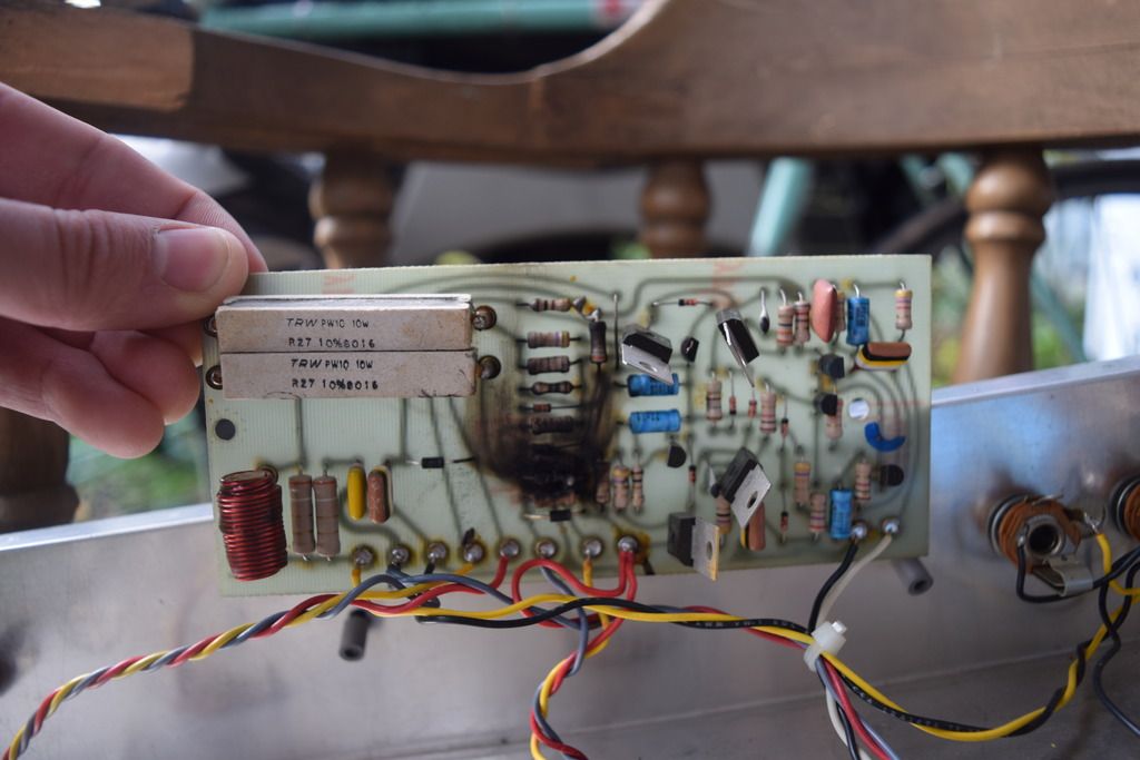
Upon opening it, I found this:
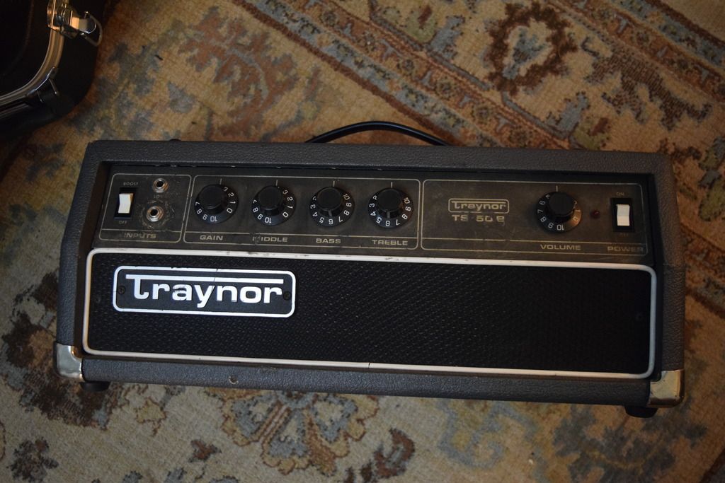
The TS50B:
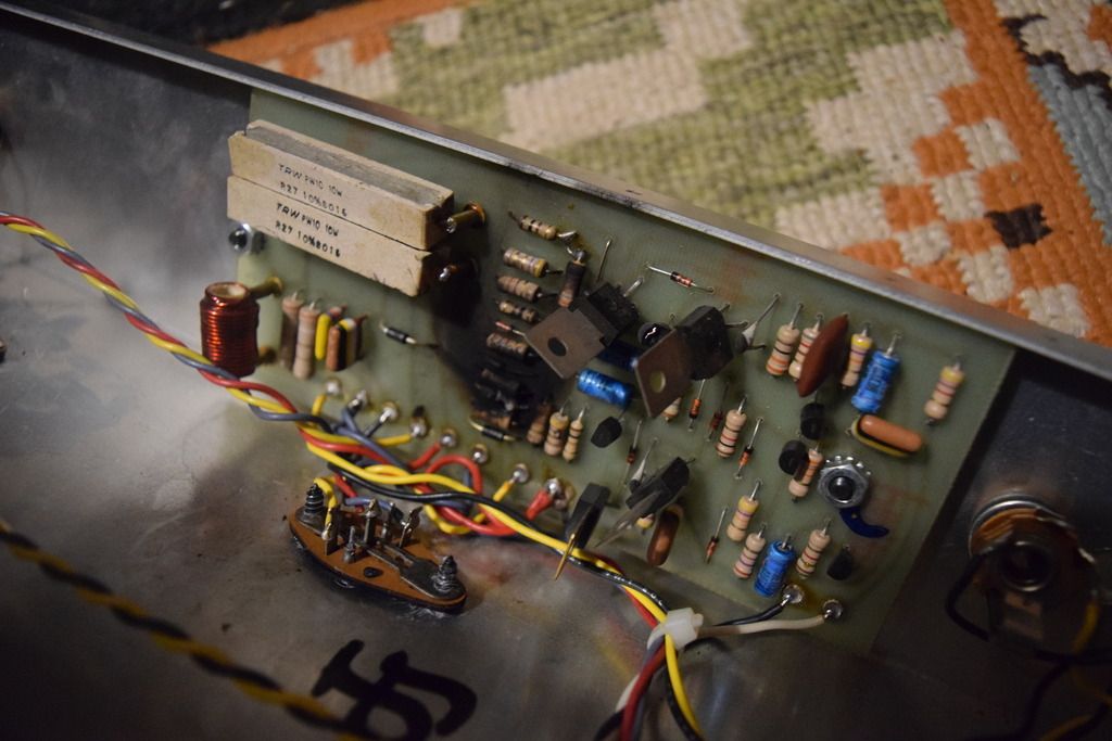
Here is the damage:
Maybe someone ran it with the wrong impedance cab? I've never dealt with something like this. Should I be worried that the transformer is fucked?
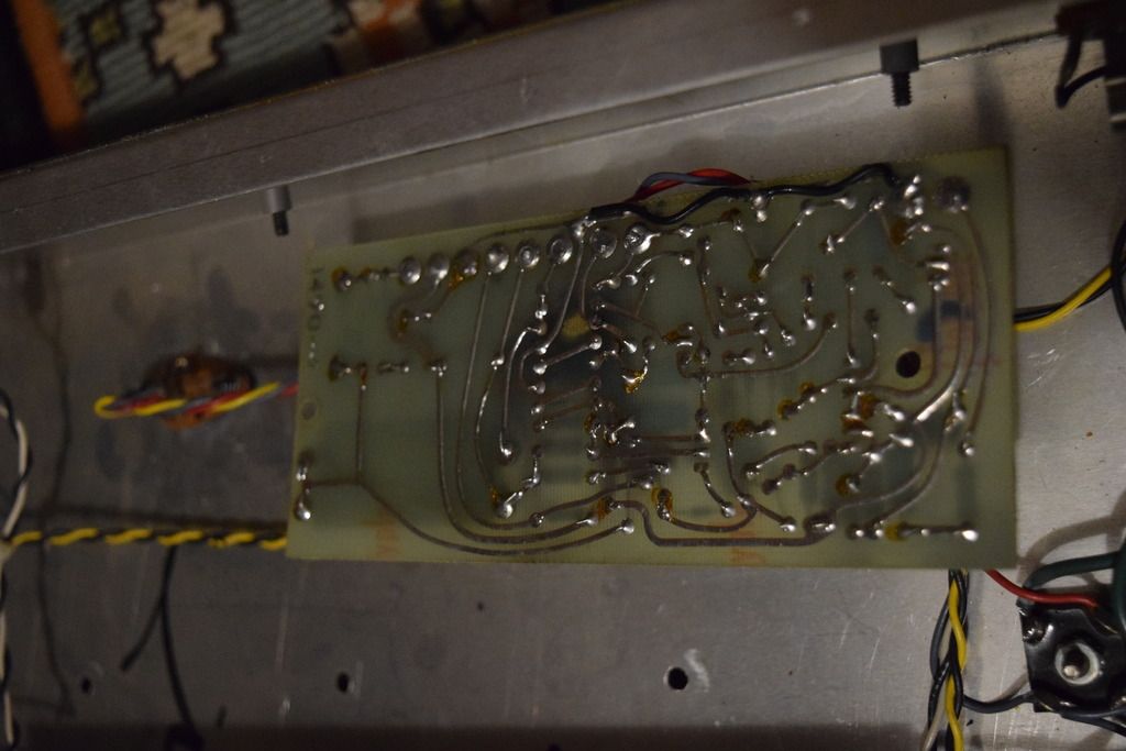
It looks like the back of the pcb is OK, so I'm hoping I can just replace these components and call it a day.
I found a schematic online, but am having trouble identifying the values of the resistors I need to replace. Could anyone make a list of those in the burnt out area?
Any pointers on to whether replacing just these resistors or if this might be a deeper problem would be appreciated!
Thanks!